You can see in many processes; we use thermic fluid to maintain the reaction temperature. In reactor jacket or coil thermic fluid circulates to maintain required temperature conditions. For, efficient reactor operation automation and controls of the reactor is very important. Moreover, same thermic fluid system you can use for reactor heating & cooling requirements also.
Generally, it is observed in our batch plants, plant operates in manual control mode. In other words, if a process parameter deviated from desired value, plant operator takes necessary action to restore it.
This manual control causes huge variation in the process parameters. In result this deviation is source of many inefficiencies and losses in the process. Like, high batch cycle time, low product yield and in some cases where process is very sensitive, we face total batch failure also. So, we can see all these are cost to the business.
So, in this article we will discuss the automation and controls of a thermic fluid heating system for a batch reactor. For this purpose, we will take an example of bulk chlorination reaction for methyl-pyridine.
Table of Contents
Process Details
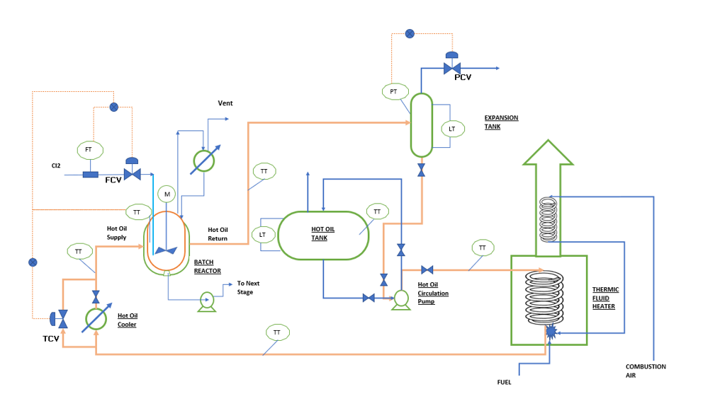
To understand the process, you can refer below figure. Here, we have one glass lined jacketed reactor with agitator. This is a batch process and reaction take place in a solvent base having normal boiling point around 208 0C. First, we charge organic solvent into the reactor and heat up the reactor mass. Subsequently, we charge methyl-pyridine and heat up the reaction mass to 180 0C. This we do by circulation of hot thermic fluid in reactor jacket. After achieving reaction temperature chlorine gas purging starts under agitated condition. Our requirement is to maintain the reaction temperature around 185 ±2 0C, this is atmospheric pressure reaction.
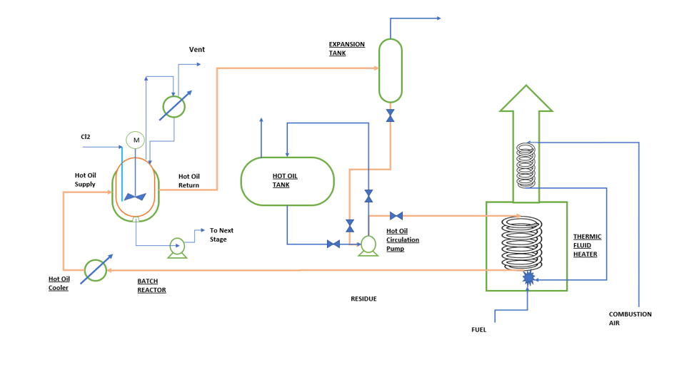
In above system you can see hot oil circulation pump circulates thermic fluid via thermic fluid heater coil. In heater coil this thermic fluid absorbs heat from the firing of fuel (i.e., FO, NG, Electricity or Coal). After heating up, this hot oil supply heat to the reactor and outlet of reactor jacket goes into the expansion tank. From expansion tank this colder oil again feed into the thermic fluid heater coil. This way this system continues to work.
Parts of Thermic Fluid System
In above figure you can see the various parts of a thermic fluid heater. We will discuss these parts one by one as follows:
Heater or Furnace
This is the main component of a thermic fluid heating system. Here we supply heat to the circulating thermic fluid. This heat we can supply through electric heaters or direct firing of fuels in a furnace.
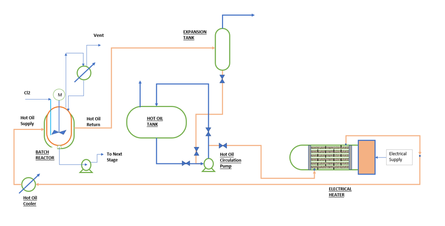
Electrical Heaters
In case of electric heater thermic fluid remain in shell side and tubes contains electric heating elements. When we supply electricity to these heating elements they heat-up and supply heat to the circulating thermic fluid inside the shell. This type of heater provides neat and clean service for the plants. Moreover, operation is also very easy in comparison with direct fired furnace. But in this case operating cost is high and huge electricity supply is required. Therefore, this is a good alternative for small capacity heating requirements say around < 1000 kW.
Direct Fired Heater
In direct fired heater we fire fuel inside the furnace body and heat is absorbed by the circulating thermic fluid inside the furnace coils. This fluid can be furnace oil, natural gas or coal. However, natural gas is the cleanest fuel among all three options. In comparison with electric heater, direct fired heater require lots of controls for efficient of safe operation of the furnace. These controls include fuel flow control, combustion air control, stake temperature and excess air control etc. When we compare this with electrical heater, there we have one control which cuts the electricity supply if hot oil supply temperature goes beyond set point. To understand direct fired heater operation and controls you can refer to the figure in Process Details section.
Hot Oil Tank
In thermic fluid system hot oil tank is required for thermic fluid storage and dumping. When I say dumping it means during plant shutdown or in case of any leakage, we need to drain complete thermic fluid from the system. This we do for the maintenance or repair work.
Hot oil tanks should be provided with a proper size vent. And the vent of this tank we should connect to a hot oil vent condenser. You must take care the expansion of thermic fluid during finalizing the volume of hot oil tank. For example, if you take 1 m3 volume of thermic fluid at atmosphere temperature then at 250 0C it will expand by around 20%.
Furthermore, we should provide proper insulation to the tank. When we dump the oil, it is very hot, so for personal safety insulation is must.
Hot Oil Expansion Tank
As you can see from name itself, the service of this equipment is to take care the expansion of thermic inside the system. We install this equipment at highest level inside the plant. We should ensure that the elevation difference between expansion tank and the highest-level consumer is minimum 3 meters.
When we do start-up of the thermic fluid system, heating is done slowly. This we do to vent off the moisture and non-condensable present in the fresh thermic fluid. Therefore, being at the top most level, expansion tank vent takes care for this requirement.
Also, expansion tank level indicator tells us about the level of thermic fluid into the system. In case of any leakage in the system, expansion tank level will come down and we will get an alarm to take appropriate action.
Circulation Pump
Thermic fluid circulation pump operates at high temperature (i.e., 260 – 380 0C) and pressure around 11.0 bar. Therefore, pump should follow API 610 latest standards to avoid any process failure and hazardous.
Pump installation should be in such a way that it is free from connecting piping thermal expansion stresses. Otherwise, it will create misalignment in mechanical assembly and may cause frequent seal failure and leakages.
Thermic Fluid
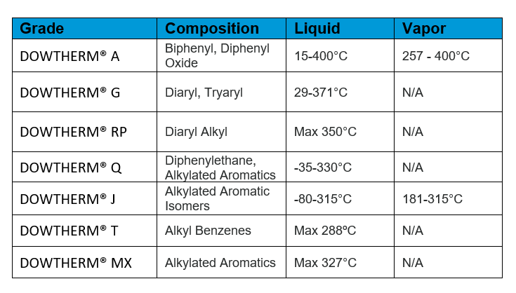
If pump is the heart then, thermic fluid is the blood for a thermic fluid heating system. Based on the process heating requirement we select suitable thermic fluid. A heat transfer fluid is a eutectic mixture of two organic compounds or a single organic compound as mentioned in below table. These in case of mixture, compounds have practically the same vapor pressures, so the mixture can be handled as if it were a single compound. Below table can guide you to understand various types of thermic fluids.
Why Automation is Required?
So, we have discussed our process setup and thermic fluid heating system also. Now we will develop automation and controls for the reactor heating system. First, we need to understand the importance of reactor temperature control. As we know all reactions are temperature dependent. And, to achieve optimum selectivity and yield, we need to maintain the reaction temperature in optimum range.
In the absence of the efficient automation & controls we will observe huge variation in reactor temperature. When temperature is lower side conversion will be lower and by-products will form. Moreover, at higher temperatures then optimum, we will get tar formation and high boiling unwanted compounds. Below is the control charts for reactor temperature variation with and without automation for your reference.
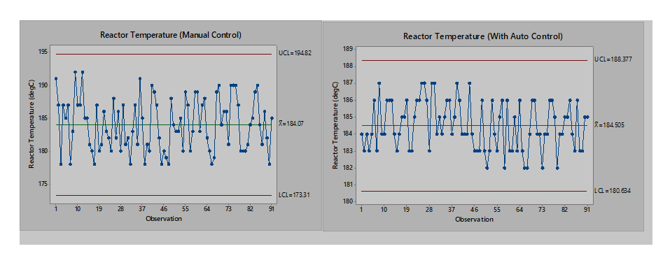
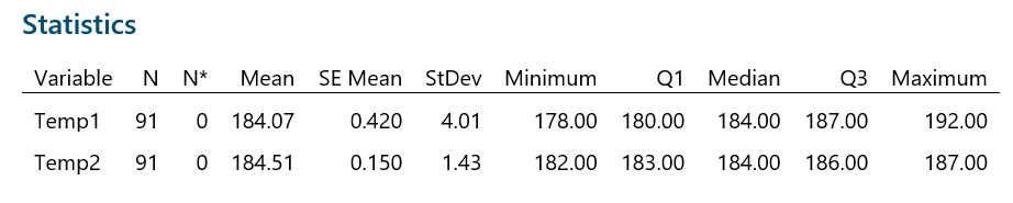
From above control charts and table, we can see the impact of the manual control & process automation. When we control reactor temperature manually, we observe huge variation (i.e., Temp1 variable). Reactor temperature oscillates between the range 178 – 192 0C and standard deviation is also high 4.01 0C.
When we provide proper automation and controls to maintain the reactor temperature. Now manual intervention is not there in reactor operation. The difference is evident, you can variation is very low (i.e., range is 182 – 187 0C and standard deviation also reduced from 4.01 to 1.43 0C).
Therefore, we can see the impact of auto-control on reactor performance. This reduction in temperature variation will result in higher reactor yield. Moreover, reactor productivity will increase due to low batch cycle time. Because when reactor temperature oscillates too much, we stop the feed and wait till the temperature return back to normal state. And, this increases the overall batch cycle time of the process.
Automation & Controls for Batch Reactor Heating System
So, to understand the automation and controls for a batch reactor system, you can refer to the below figures. We can divide our control system in two parts. First is for thermic fluid system and second is for our batch reactor temperature.
Automation & Controls for Thermic Fluid Heater
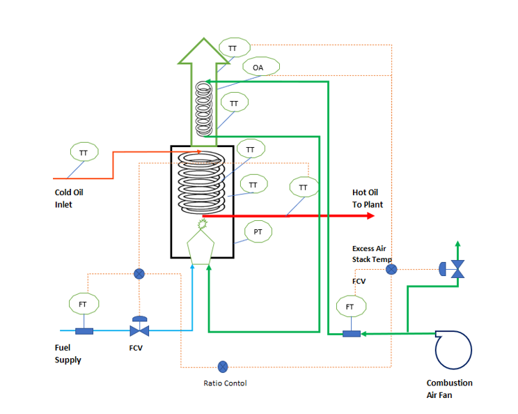
In below figure we see the various automation and controls for the smooth operation of a thermic fluid heater.
To control fuel flow rate, we use FCV in fuel feed line. Apart from this the fuel flow rate should be in cascade control to maintain the thermic fluid outlet temperature from the furnace. We should provide a ratio control between fuel feed flow and combustion air flow. This will adjust the combustion air flow automatically in case there is any variation in fuel feed flow.
Combustion air flow control require a control valve in vent line at the discharge of combustion air fan. This controller is very important for efficient and safe furnace operation.
Other important controls are stake temperature and excess air control. If these values go beyond set point combustion air flow control valve will take action to control them. To measure excess air in flue gas we provide oxygen analyser in furnace stack. Other instruments like PT gives the back-pressure indication at furnace inlet. Various temperatures transmitters we need to monitor the radiant section, tube skin, convection section temperatures. These parameters are very critical for the furnace safety.
Automation & Controls for Reactor Temperature
To understand the reactor temperature control & automation you can refer below figure. While thermic fluid heater control and automation will take care to supply the thermic fluid at a stable temperature with minimum variation. So, to control the reactor temperature variation we need to control the hot oil supply flow rate and temperature both.
First, we need to understand the sources of temperature variation in a batch reactor. Since this reactor is semi-batch type process, where we have charged one raw material and chlorine gas we are feeding continuously. Therefore, any variation in chlorine feed rate will affect the reaction rate and subsequently heat balance. When chlorine gas flow rate is at lower side reactor temperature will go down as reaction rate will decrease. On other side at higher chlorine gas flow rate than set point value, reaction rate will increase and reaction mass temperature will go up.
Other than this variation in temperature of circulating thermic fluid in reactor jacket is another source of reactor temperature variation. For this we have already discussed control and automation for thermic fluid heater in previous section.
Details of Control Strategy
So, we need automation & controls to deal with reactor temperature variations. We can provide various controls and automation as follows:
- Flow control valve in chlorine feed gas line, this will ensure chlorine gas flow control to the reactor. This flow control will be in cascade control with the reactor temperature also. In case of reactor temperature variation chlorine gas flow will change accordingly.
- To control the reactor temperature, we provide a temperature control valve in the hot oil cooler by-pass line. In case when reactor temperature goes below set point value, this valve will open to increase the hot oil supply temperature. And for the situation when reactor temperature goes up this by-pass TCV will close down to decrease the hot oil inlet temperature to the reactor jacket.
- Hot oil cooler uses cooling water for cooling the oil. We install a manual valve at hot oil cooler outlet to provide sufficient back pressure for the efficient operation of TCV.
- A pressure control valve (PCV) at expansion tank vent control the system pressure according to circulating thermic fluid temperature.
- Level indicators for Hot Oil Tank and Expansion Tank to monitor the levels.
Conclusion
So, we got the idea for automation and control for a batch reactor heating system. This way you can provide automation and controls to batch reactor and thermic fluid heating system. This will ensure the stable reactor operation with minimum variation in the reactor operating temperature.
We can also look into the feed forward control option for reactor temperature control. Any variation in chlorine gas flow will be taken as input to the hot oil inlet temperature control (TCV). This way TCV will take appropriate action in advance to mitigate the reactor temperature variation. For this purpose, we need to develop a correlation matrix between chlorine gas flow rate and reactor temperature.
This way you can implement smart control strategies, which will eliminate the human interventions in process. In result process will be stable with minimum variation in operating parameters. Moreover, variable cost of production will come down and we will get consistent product quality and production capacity.
Thanks for reading and looking forward for your feedbacks.