In many chemical manufacturing processes, ammonia is used as a reactant and generally we feed it in excess than theoretical required. After reaction part of the ammonia reacts and unconverted ammonia comes out from the reactor with product. For the economic feasibility and moreover environmental pollution abatement we need to recover this unconverted ammonia. Therefore, we need to remove this unconverted ammonia from outgoing off gases before venting or sending for incineration.
In this article we will consider an example of a chemical manufacturing process and will design a process for unconverted ammonia recovery.
Table of Contents
Description of the Process
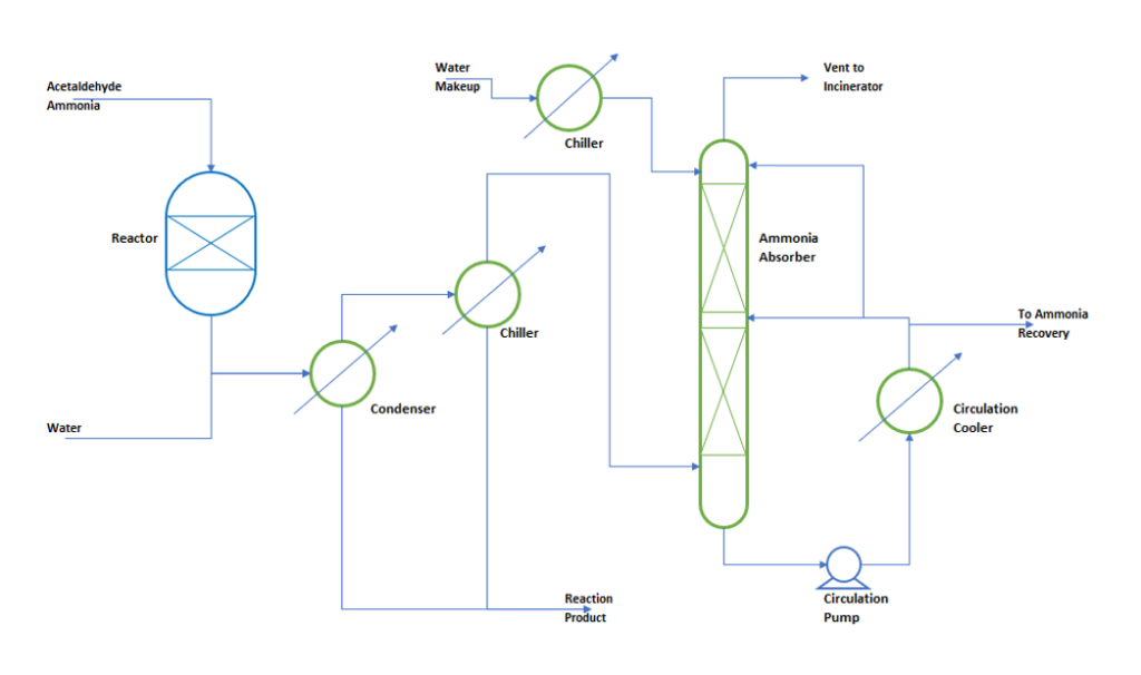
In our case we are considering a process where a limiting reactant acetaldehyde reacts with ammonia at 450 0C. During reaction acetaldehyde conversion is 100% and ammonia is being feed around 3 times by weight of theoretical requirement. After reaction product gases goes to a condenser and subsequently to a chiller to condense the product and other condensable components. From condenser uncondensed gases goes to ammonia absorber to scrub the ammonia from outgoing non-condensable gases. In absorber column we use water to absorb the ammonia gas. Since ammonia absorption is an exothermic process, therefore we need to remove heat of absorption from the absorber column. Hence, Absorber column temperature is maintained by a circulation cooler. To understand the process, we can refer below figure.
Design Basis for the Process
For our example we will consider below parameters:
Acetaldehyde Feed Rate : 1000 kg/h
Theoretical NH3 Requirement : 300 kg/h
Actual NH3 Feed Rate (3 times) : 900 kg/h
Non – Condensable in product : 150 kg/h (other than unconverted NH3)
Condenser process outlet temperature : 45 0C
Reactor Chiller process outlet temperature : 20 0C
Absorber bottom temperature : 45 0C
Absorber top temperature : 30 0C
Cooling water supply temperature : 32 0C
Chilled water available temperature : 7 0C
Ammonia solubility in Absorber bottom : 16 % by wt. (@ 45 0C)
Ammonia concentration in reaction product : 7.2 % by wt.
Absorber efficiency for NH3 absorption : 95 % by wt.
Heat of solution for NH3 in water : 521 kcal/kg
Make up water is pure and temperature after chiller is 20 0C. At absorber inlet we have negligible organic contents. Absorber feed contains non-condensable, 6.7 % water & unconverted ammonia.
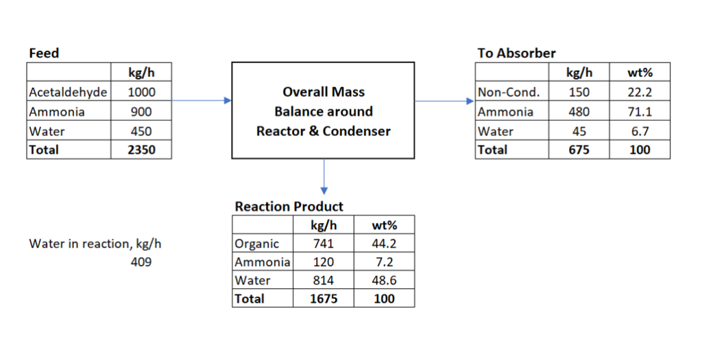
Material Balance around Reaction Section
Now we will estimate the flow rate and composition into the absorber column.
Total mass at the outlet of reactor = 1000 + 900 + 450 = 2350 kg/h
Moles of acetaldehyde in feed = 1000/44 = 22.73 kmol/h (molecular wt. acetaldehyde = 44 kg/kmol)
Since acetaldehyde conversion is 100%, therefore oxygen will be converting into water. One kmol of acetaldehyde contains one kmol of oxygen. Therefore, we will get 22.73 kmol/h water from reaction or 22.73*18 = 409 kg/h.
Unconverted ammonia in this stream = 600 kg/h.
Based on our design basis and assumptions, below is the material balance around Reactor, Condenser & Chiller.
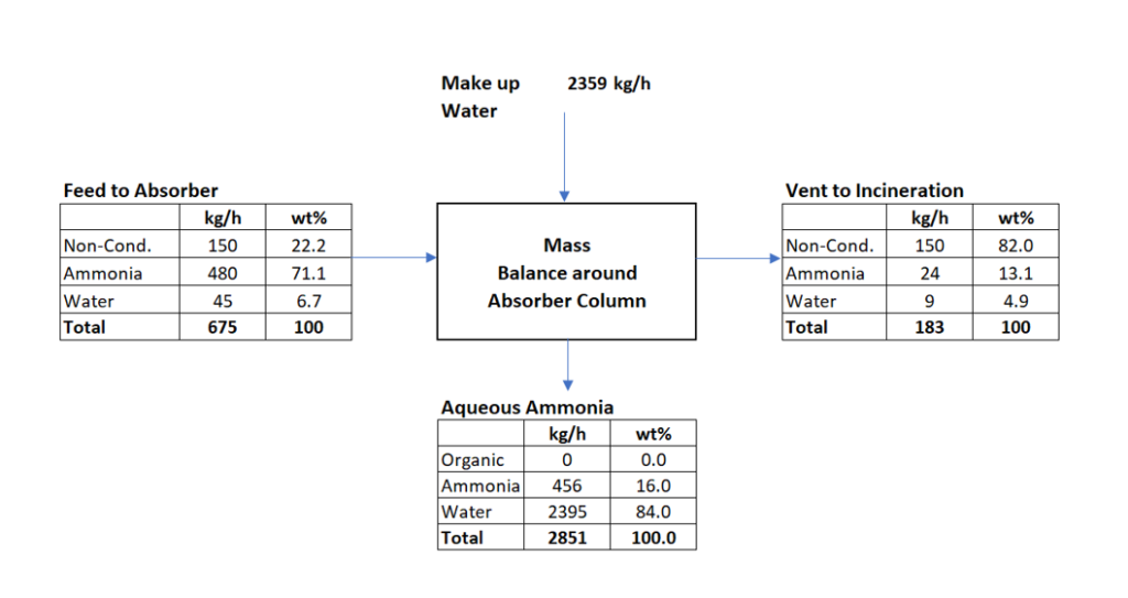
Material Balance around Absorber Section
We have estimated the flow rate and composition at absorber inlet as shown in above figure. Now we will do the material balance around absorber column. We will estimate makeup water requirement and pump circulation rate. In design basis we have considered ammonia absorption efficiency 95 % by wt. Therefore, in absorber vent ammonia quantity = 480*0.05 = 24 kg/h and in absorber bottom outlet is = 480 – 24 = 456 kg/h. This ammonia will be absorbed in water to produce 16% by wt. ammonia solution. This aqueous ammonia will be going out from the absorber column bottom. Subsequently, the 16% ammonia solution goes to ammonia recovery column. There we recover ammonia and recycle back to the reactor. Below is the material balance for the absorber column system.
Feed to the absorber = 675 kg/h (NH3: 480 kg/h)
Heat Load & Pump Circulation Rate Estimation
From above material balance we can get below information
Make up water requirement will be = 2359 kg/h
16% by wt. aqueous ammonia solution out from absorber bottom = 2851 kg/h
Vent from absorber column will be = 675 + 2359 – 2851 = 183 kg/h
Absorber bottom temperature required = 45 0C
Circulation cooler outlet temperature = 38 0C
Circulating liquid heat capacity = 1.0 kcal/kg 0C
Heat capacity of inlet gas to absorber = 0.48 kcal/kg 0C
Vent gas heat capacity from absorber = 0.45 kcal/kg 0C
Now we will calculate the heat load on circulation cooler, for this we will apply heat balance around ammonia absorber column.
Q = heat in with feed + heat in with makeup water – heat out with vent gas + heat generation due to ammonia absorption
For all input output streams heat estimation is relative to absorber bottom temperature (i.e., 45 0C, this will make heat out with bottom stream zero as temperature difference is zero)
Q = 675*0.48*(20 – 45) + 2359*1.0*(20 – 45) – 183*0.45*(45 – 30) + 456*521 = 169266 kcal/h
Now we can calculate the circulation rate of pump to remove heat load as below.
W = Q/(1.0*(45 – 38) = 169266/7 = 24181 kg/h
W’ = 24181*1.20/1000 = 29 m3/h (@ 20% extra and 1000 kg/m3 density)
Utility Requirement Estimation
As we have done material and energy balance in previous sections, now we can workout the utilities requirement for our process.
Cooling water requirement for circulation cooler:
Heat load on cooler, Q = 169266 kcal/h
Cooling water required at 38 0C cooling water outlet temperature, Wc = Q/(1.0*(38 – 32) = 169266/6 = 28211 kg/h = 28.2 m3/h
Chilled water requirement for makeup water chiller:
Heat load on chiller at 38 0C chilled water inlet temperature, Q1 = 2359*1.0*(38 – 20) = 42462 kcal/h taking 20% extra, Q1’ = 50954 kcal/h.
Chilled water required at 13 0C chilled water outlet temperature, Wch = Q1’/(1.0*(13 – 7) = 50954/6 = 8492 kg/h = 8.5 m3/h
In terms of Tons of Refrigeration = Q1’/3024 = 16.85 TR
Power requirement for Circulation Pump:
Required capacity of the pump is, W’ = 29 m3/h = 29*1000 = 29000 kg/h
Considering absorber height 15 meters from floor level and head loss in circulation cooler, piping and fittings 10 meters. Total required head will be 15+10 = 25 meters.
Therefore, theoretical power for the pump is, P1 = (29000/3600)*9.81*25 = 1975.6 W.
Taking pump efficiency 70% and motor efficiency 90% actual power required will be, P1’ = P1/(0.7*0.9) = 3136 W = 3.136 kW
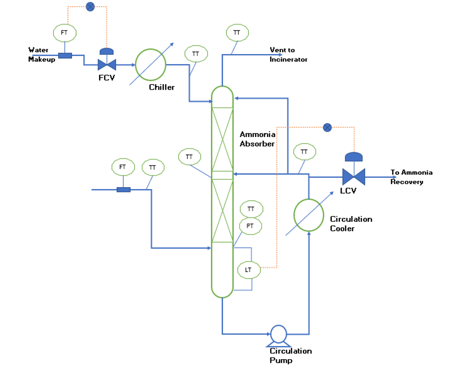
Process Control & Automation
For smooth and stable operation of the absorber column we need proper instrumentation and controls in place. To understand the control philosophy for efficient operation of absorber column you can refer to below figure. This figure shows all the required instrumentations and controls, details are as below.
In gas feed line we need flow meter and a temperature transmitter to monitor the input variable variations.
In makeup water line we require flow meter and flow control valve to maintain constant makeup flow rate. Also, a temperature transmitter is needed to monitor and maintain the makeup water temperature to the absorber column.
To monitor absorber column parameters, three temperature transmitters (i.e., bottom, middle & top). Apart from this we need a pressure transmitter at the bottom of the column to monitor stable hydraulic conditions inside column.
A temperature transmitter is required at the outlet of the circulation cooler. Moreover, this will help us to monitor the performance of the circulation cooler.
A level control valve and level transmitter are required to maintain the constant level and continuous withdrawal of aqueous ammonia solution.
Various alarms on flow, temperatures, pressure and level enable us to take prompt corrective actions for safe and efficient operation of the absorber column.
Conclusion
In this article we discussed the process design for ammonia absorber column. Also, we carried out material and heat balance around the absorber column. Moreover, we estimated the utilities requirements for the system. Furthermore, we discussed the instrumentation and control for absorber column.
Thanks for your reading and feel free to contact in case of any clarification.
Sir,
Will you please wrote an article on feasibility study for continuous process, with case study.