We can see single stage distillation method application in our chemical process industries. This is a very simple unit operation, which consists only single stage. In this method we remove all the vapour as such, or is condensed as a product. We can perform single stage distillation process in batch and as well as in continuous mode also. When we operate in batch mode, we call it a Differential Distillation, while in case of continuous operation it is known as flash distillation or single stage equilibrium distillation.
Generally, we use single stage distillation system in upstream of the multistage distillation or fractionation column. If I say specifically, we use this method to remove all the volatile components from a crude mass having fouling, chocking or polymerizing nature and is non-volatile salt. Therefore, using single stage distillation setup we get rid from this residue and condensate or vapor goes for further fractionation. This way we can avoid the problems of distillation tower and reboiler chocking during distillation.
Let us discuss these methods in detail in subsequent sections.
Table of Contents
What is Differential Distillation?
So, first let us understand what is a differential distillation? To get insight about the setup you can refer to below figure. In this there is a batch kettle, in which we charge the mixture. To supply heat there is a u-tube bundle inside the kettle. And, in this u-tube bundle we use steam or thermic fluid as a source of heat supply.
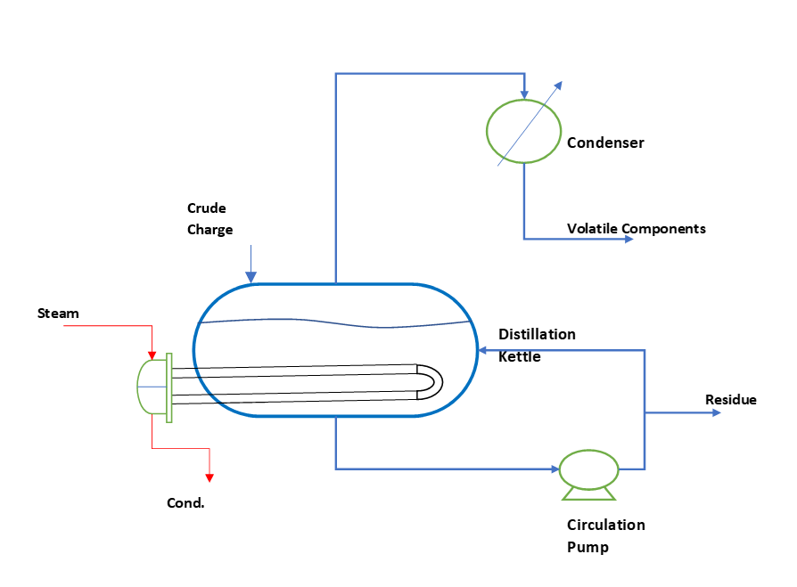
So, in above figure we can see we charge the crude material in the kettle. And, supply heat to this kettle mass through u-tube bundle. Also, we provide a circulation pump or agitator to keep the kettle mass in well mixed conditions. Subsequently, kettle mass boils up and vapor of volatile components is either condensed and collected or directly fed into the second multi-stage distillation column. During the process kettle temperature keep on increasing as concentration of low boiling volatile components continuously decreases.
As this process consists of only a single stage, which is our kettle only. Therefore, complete separation is not possible, so at the end of process there will be some quantity of volatile components in the residue. Hence, the application of differential distillation is restricted to some situations, which can be as below:
- Some situations, where a preliminary separation is required. Specially in the cases of crude mass containing chocking, non-volatile or salts. We use differential distillation and recover volatile organic mixture and feed it to a more rigorous distillation column for further separation.
- We can use this method for the separation, where high purities are not required, it is a preferable choice because of low capital investment.
- Also, this is a better option, in cases where the mixture is very easily separable or in other words relative volatility of mixture is very high.
Dynamic Behavior of Batch Kettle
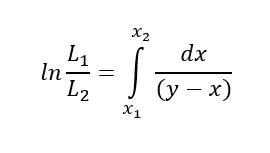
So, we can see this differential distillation is dynamic in nature. During the process, with time distillation mass and composition in kettle continuously keep on changing. The composition change during the differential distillation of a binary mixture is given by the Rayleigh equation.
Where, Initial charge of liquid in kettle, moles, L1
After distillation residue mass, moles, L2
mole fraction of volatile compound in charged liquid, x1
volatile component composition in residue, mole fraction, x2
mole fraction of vapor and liquid at equilibrium, x and y
Based on the heat input rate in kettle, we can estimate the boil-up rate. And, composition in kettle residual material we can estimate using above equation. For estimating distillation time, we use vapor/condensate collection rate.
In next section we will discuss flash distillation process.
Flash or Equilibrium Distillation
In contrast with differential distillation method, flash or equilibrium distillation we frequently conduct in continuous mode. To get the feel of this process you can refer the below figure. Here, we have a flash vessel and to supply heat to the feed there is a feed preheater. The feed enters into flash vessel through a valve where we reduce the feed pressure. This flash vessel is actually a separator in which the liquid and vapor produced by the reduction in pressure. Here we provide sufficient residence time to reach at vapor & liquid equilibrium state.
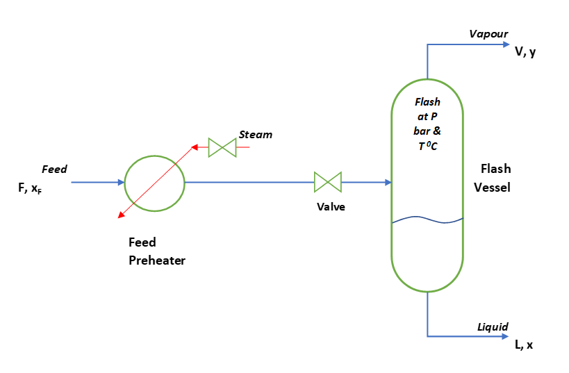
From flash vessel, vapor goes from the top, which we usually condense or connect it to a distillation column for further purification. While liquid leaves from the bottom and goes for next level of processing.
Material Balance for Flash Distillation
So, to understand the fundamental behind flash distillation, let us assume a binary mixture of components A and B. However, flash distillation setup may contain many components. As you can see in above figure of flash distillation process. Here, is a feed stream having F moles/h and contains mole fraction xF of component A. Also, please note here component A is more volatile.
After preheat this feed passes through a valve to reduce the pressure. Subsequently, this feed enters into the vessel and V moles/h of vapour forms. This vapour contains y mole fraction of A. While, from the bottom S moles/h of liquid with x the mole fraction of A comes out.
So, we can write an overall mass balance, F = V + S
In this vessel vapour leaving is in equilibrium with the inside liquid. Also, the component mass balance for A will be, F*xF = V*y + S*x
Thus, we can combine above two relationships to get,
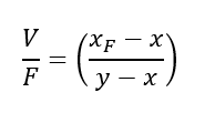
We can rearrange the above equation to get,
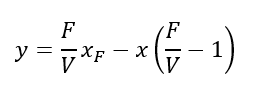
So, we got a straight line having slope of -((F/V) – 1) = -(F – V)/V = -(S/V).
Heat Balance for Flash Distillation
The quantity of vapor fraction depends upon the heat supplied to the feed and pressure drop across the valve. So, we can write an enthalpy balance for the flash distillation system as below,
F*HF = V*HV + S*HS
Where, HF, HV & HS are the enthalpies/mole of feed, vapour and liquid streams respectively.
Hence, to get vapour generation rate we can rearrange above equation to get,
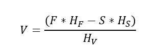
Since, F = V + S or S = F – V, substituting value of S in above equation we get,
So, from we can see higher the enthalpy of feed for given conditions we get higher fraction of vapor. Moreover, for a given feed condition, we can increase the vapor fraction vaporized by lowering the pressure in flash vessel. This is so, because at reduced pressure, enthalpy of vapor will be low.
Next, let us do process calculations for a flash steam generation system from high pressure steam condensate.
Steam Condensate Flash Steam Generation System
In our chemical plants we use steam to supply heat to distillation columns, reactors, dryers, preheaters, multiple effect evaporators, etc. We can categorize the steam pressures used inside plants like low pressure (< 2 kg/cm2g), medium pressure (>2 and < 8 kg/cm2g) or high pressure (> 8 kg/cm2g). Moreover, this steam is mostly at saturation conditions, so that it can provide heat to the process immediately after condensation. So, after condensation this steam condensate is available at high temperature and pressure. We can generate low pressure flash steam from this condensate and which can be used inside the plant. Apart from this we can generate low cost refrigeration from waste steam using a VAHP (Vapour Absorption Heat Pump).
Let us take an example, in a plant 18000 kg/h steam condensate is available at 8 kg/cm2g saturated condition. We want to produce 2 kg/cm2g flash steam from this condensate. We can see in below figure. To control the flash vessel pressure a PCV (Pressure Control Valve) is fitted in vapor line. While, to control liquid level inside the flash level we use LCV (Level Control Valve) installed in liquid line. After steam condensate flashing, liquid from bottom is continuously pumped to the boiler. Where it is used as a boiler feed water after required treatments. While flash steam is connected into the 2 kg/cm2g steam supply header.
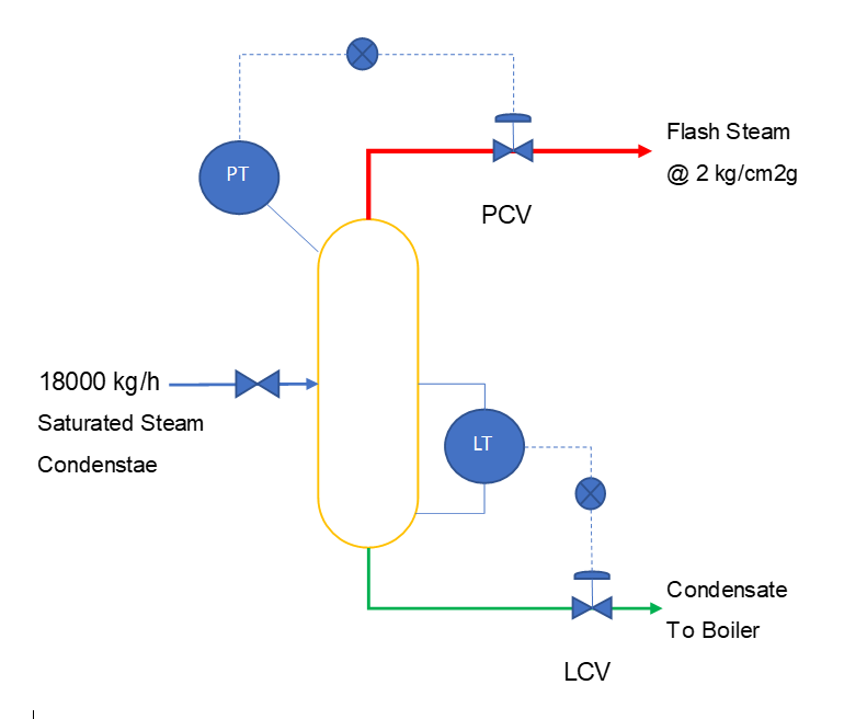
| 8 kg/cm2g condensate feed rate, F = 18000 kg/h |
| Enthalpy of 8 kg/cm2g condensate, HF = 176.8 kcal/kg |
| Enthalpy of 2 kg/cm2g condensate, HS = 133.7 kcal/kg |
| Flash Steam Enthalpy at 2 kg/cm2g, HV = 648.7 kcal/kg |
| Total enthalpy of condensate, F*HF = 3183000 kcal/h |
| Flash steam generation will be, using Equation – 5, |
| Flash steam generation @ 2 kg/cm2g, V = 1508 kg/h |
| Flash condensate to boiler @ 2 kg/cm2g, S = 16492 kg/h |
Conclusion
So, we got insight about two very important techniques namely differential distillation and flash distillation. Both of these are very simple to operate and easy in installation. We can look into our processes and wherever it is possible we should use them. As, this can minimize the load of complex distillation and moreover, distillation column fouling and chocking problem can be reduced or altogether eliminated.
We also discussed about the flash steam generation system using medium and high-pressure steam condensate from plant. This is a good opportunity to utilize the available waste heat. Otherwise, we find there are lot of flash steam keep on venting into the open atmosphere. Which is very harmful for plant steel structure, because of its corrosive nature.
Thanks for your reading, looking forward for your comments.